


ZnPP AG Power Condensers
You have purchased the ZnPP Box Type Power Capacitor, which is produced by Kondaş Capacitors under the standards of TS EN 60831 & IEC 60831. For maximum benefit and safety, please follow the instructions listed below.
WARNING: After disconnecting the capacitors from the power source, wait according to the discharge time which is stated on capacitor label, then short and ground the capacitor using an insulated cable. Shorting should be terminal to terminal and terminal to case.
Assemble the capacitor with the mounting parts as shown in the photo below. When assembling, the maximum tight power applied on bolt nuts should be 0.4 kg.m
The capacitor units should always be placed on a vertical position
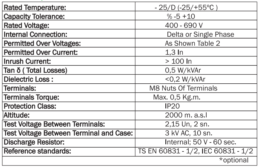
Avoid using the product in over ambient temperatures which is stated on capacitor label
Open the plastic cover before connecting the terminals. Use conductive material that are compatible with terminals which are listed below.
. Earthing of the capacitor shall be made properly.
The first terminal nut on the bushings are fixed with 0.5 kg.m of power. Use two wrenches during connecting the conductors to the bushings, one is for fixing counter side for first nuts and fix all the nuts with 0.5 kg.m. The terminal nuts shall be regularly checked in order to avoid a loosening up. (Loose connection on terminals cause overheating and therefore defects in time)
Select the PFC contactors in relation to the AC2-AC3 rated voltage (not Ith)
On automatic compensation; the contactors that command the first step group capacitors should be selected 1.5 times the rated voltage of the capacitor. For the remaining steps, the multiplier is 1.25
The fuses on the feeder should be selected 1.7 times the rated current of the capacitor
Feeding panel or other switches or circuit breakers should be selected 1.3 times the rated current of the capacitor
Environment that the capacitors work in should be dry at all times and ventilated regularly
On automatic compensation, select the power of the steps in accordance to the need of the system
The current transformer that will be connected to the reactive power control relay should be selected in accordance to the sort of premise that is intended to be compensated.
The current transformer should be connected before the capacitors on the feeding line and should be located at the primary entrance of the building.(best just after the Energy Meter)
The ratio of the current transformer and the intended cos f Q should be entered to the reactive power control relay. Other necessary settings should be altered in relation to the instructions of the relay.
| 3 Phase Capacitor Power (kVAr); (on 1 phase, use the cable for the one on upper tier) |
Flexible Cable Compatible with Standards (mm2) |
Busbar CU (mm2) |
| 1 | 3 x 2.5 | 12 x 2 |
| 1.5 | 3 x 2.5 | 12 x 2 |
| 2.5 | 3 x 2.5 | 12 x 2 |
| 5 | 3 x 2.5 | 12 x 2 |
| 7.5 | 3 x 2.5 | 12 x 2 |
| 0 | 3 x 4 | 12 x 2 |
| 12.5 | 3 x 4 | 12 x 2 |
| 15 | 3 x 6 | 12 x 2 |
| 20 | 3 x 10 | 12 x 2 |
| 25 | 3 x 10 | 12 x 2 |
| 30 | 3 x 16 | 25 x 3 |
| 40 | 3 x 25 | 25 x 3 |
| 50 | 3 x 35 | 25 x 3 |
| 60 | 3 x 50 | 25 x 3 |
1P12Z0001


There are no reviews yet.